|
|
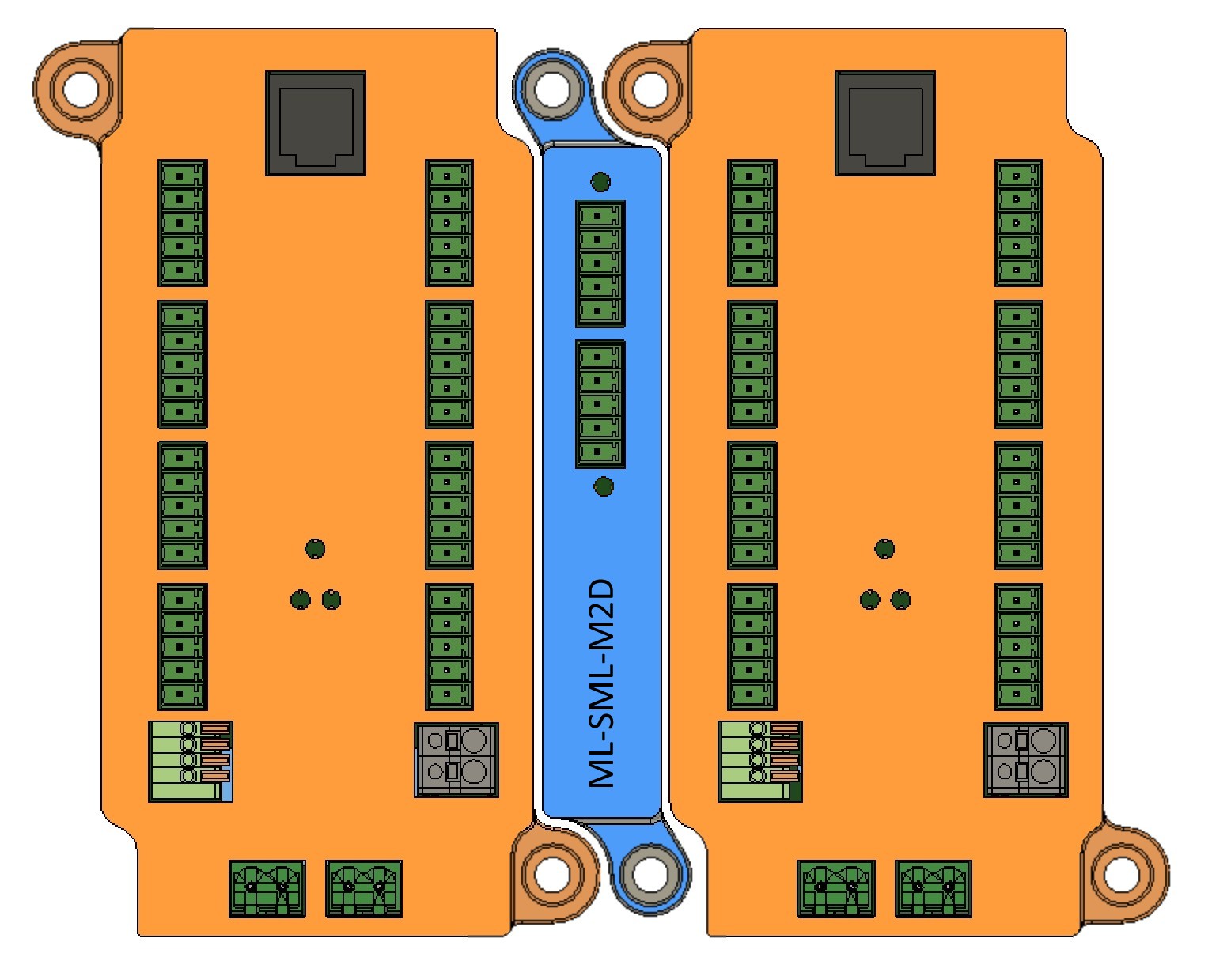
ML-SML-M2D
In Leviton 47605 format - with PSE-8D
|
|
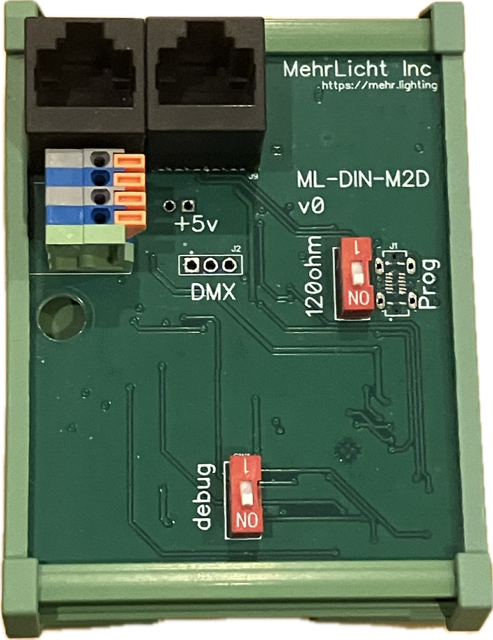
ATX LED Matter to DALI Bridge - ML-SML-M2D or ML-DIN-M2D
- Matter communication standard
- 64 DALI addresses
- 16 DALI groups
- Automatically assigns DALI addresses
- Automatically provides DALI bus power if no external supply detected
- Works with all Matter border routers
- Support DT6 (fixed) and DT8 devices ( tunable white )
- maintains sync between ATX LED Switches, ATX LED Hubs and Cloud control
- local and remote control
Does not require the ATX LED Hub for operation
Works with the ATX LED Hub if both are present
- does not change existing DALI addresses or configurations.
- fits into Leviton 47605 box
- Remote diagnostics of:
- DALI bus voltage
- DALI bus current
- up to 8 system power supplies ( typically 24 to 60 volts)
- WiFi quality
- Network Ping response times
- Geographic location
- Real Time Wattage
- Active / Missing devices
Specifications for ATX LED Matter to DALI
- 64 DALI devices - each can be exposed to Matter or hidden - each has a friendly name
- 16 DALI groups - each can be exposed to Matter or hidden - each has a friendly name
- 8 Power Supply devices - these are the lighting power supplies - in IM-M2D this is always 51v on all
- 1 DALI Bus device - this is the state of the DALI bus power - in IM-M2D this is either 12v or 0v
- DIN rail or SML mounting
Scheduling - handled by Matter
Error reporting - email from the device if any change in # of power supplies
Macros - only address forwarding is supported ( copy level from address/group x to y )
Address Assignment - Automatic if a new device is detected
DT6 to DT8 conversion - method to send mode change to the driver ( python script is available )
Grouping - method to assign / unassign any 64 address to any of 16 groups
8 Virtual Power Supplies devices - these are the voltages of up to 8 power supplies - read only
1 DALI Bus device - this is the voltage on the DALI bus
ESP32 Pinout / Functions
Pin
| Pin Name
| Connected To
| Function
|
3
| Enable
| S3, Pullup
| Boot
|
37
| GPIO 0
| S1
|
|
39
| IO 0
| +48v C
| measure Power Supply C voltage, gain 25
|
38
| IO 1
| +48v D
| measure Power Supply D voltage, gain 25 |
6
| IO 6
| +48v A
| measure Power Supply A voltage, gain 25 |
7
| IO 7
| +48v B
| measure Power Supply B voltage, gain 25 |
12
| IO 8
| SW1
| Operation Mode
- Close - User, full Matter Control
- Open - installer mode
|
17
| IO 9
| DA Current
| Measure Voltage during transmit
0.5 Ohm resistor, gain 1:1
|
18
| IO 10
| DA Voltage
| Message Voltage - gain 5.8
|
19
| IO 11
| DA Test
| Turns on 6.5v load to measure current
|
20
| IO 12
| DAbus power
Enable
| Enables power when High
Sources 80 mA
|
21
| IO 13
| DAbus Current Boost
| Sources 180 mA |
Power On Algorithm
onboard DALI power off.
- measure DALI bus voltage
- measure DALI bus current Set DA Test - measure current @ 6.5 volts
if Voltage is < 15 volts and current is less than 180 mA, enable +80mA current
- measure DALI bus voltage
- measure DALI bus current Set DA Test - measure current @ 6.5 volts
if Voltage is < 15 volts and current is less than 140 mA, enable 100mA current
- read bus device status and level
- check if unassigned devices
- address unassigned and leave existing unchanged
- Read UPC codes
Name unnamed devices with the friendly name of the UPC codes followed by the short address
Read Groups
Express short address and groups to Matter
-----------------------------------------------------------------------------------------------------------------------------------
Power Supply Status Reporting
4 inputs from the House Power panel
each has a gain of 25 - measurement range of 2.5 to 75 volts
a) If the input is between 44 and 75v, the that input has one power supply, with that voltage. Count each input with greater than 44v. Report the voltage
b) If the input is between 3 and 24 volts - then the number of power supplies is between 1 and 4. The calculation is:
using this method, up to 8 power supplies can be counted, the voltage of each supply is reported in a)
Voltage
| #count to add
|
1.5
| 0
|
3
| 0
|
4.5
| 1
|
6
| 0
|
7.6
| 1
|
9
| 1
|
10.5
| 2
|
12
| 0
|
13.5
| 1
|
15
| 1
|
16.5
| 2
|
18
| 1
|
19.5
| 2
|
21
| 1
|
22.5
| 3
|
Missing in Version 1
- detect UPC code and use appropriate default names
- detect groups and scenes and allow them to be named, default is group 0-15
- detect non default scenes and allows them to be named.
How to pair
insure phone is on 2.4ghz network
Apple Home - add matter device
scan QR code
how to add Alexa after Home
in Home, open home -> Bridge -> settings -> enter pairing mode -> get code
in Alexa - add other device, find matter, enter pairing code
how to add Google after home
in Home, open home -> Bridge -> settings -> enter pairing mode -> get code
in Google, add device, enter pairing code

 Uploading ....